Two test cases simulate the propagation of a solitary wave.
Two test cases simulate the propagation of a solitary wave.
Two test cases simulate the propagation of a solitary wave. The first one simulates the solitary wave on an horizontal bed in a periodic domain, while in the second one the wave collides against an end-wall. The aims of these test cases are to:
First-order solitary wave theory is used for the initial wave shape and wave velocity [1,2]. Air and water are considered.
Domain is rectangle, its opposite corner coordinates being \((0,0,0)\) and \((10,0.6)\). The solitary wave is completly defined for a given depth of water \(d = 0.3020 \ m \) and a wave amplitude \( H = 0.11 \ m\). The wave crest coordinate is located at the middle of the domain, its height being \( z=0.33522 \ m \) and celerity \( c = 1.8134 \ m.s^{-1} \).
The periodicity is set in the horizontal direction, symmetry on top and bottom boundaries.
Domain is rectangle, its opposite corner coordinates being \((0,0,0)\) and \((3,0.2)\). The depth of water \(d \) is equal to \( 0.1 \ m \), the wave amplitude \( H = 0.02 \ m \). The wave position is set at \( x=1 \ m\).
Periodicity is changed with wall on the right boundary and symmetry on the left one.
The hybrid centered/upwind scheme is used for the non linear term of the Navier-Stokes equations. VOF-PLIC method is selected for the advection equation.
Grid dimensions vary from (256x150) to (2048x1200). Time step is equal to \( 0.01 \ s \) for the first grid and decreases by a factor two as the grid is refined. The physical elapsed time is equal to \( 45 \ s \). According to the wave theory, at this time, the position of the peak is \( x=81.603 \ m\).
Grid dimensions vary from (512x64) to (2048x256). Time step is equal to \( 0.00035 \ s \) for the first grid and decreases by a factor two as the grid is refined. The theoritical expected maximum wave height against the wall can be predicted by analytical developments [3]: \( z_m = 0.140206 \ m \).
To check the symmetry of the code, a rotation of the configuration has been tested and produces similar results (small differences are explained by the direction splitting in the VOF-PLIC method). Both flow directions are checked in the validation script of the code. To save computational time in the validation process
Thanks to the celerity of the initial wave, one can estimate the theoritical distance it propagates during the time of the simulation. We compare this position to the final position of the simulated wave crest, and the difference between the theoritical and numerical crest height.
The maximal wave height against the wall is measured and compared to the predicted one (as well as the the corresponding time).
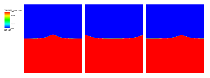
Figure 1 presents the volume fraction of water at different times of the simulation, initial, when the wave goes through the periodic boundaries and final time after 8 passages through the horizontal boudaries.

Solitary wave height and position after 45s are presented for different mesh size Table 1.
| Mesh | Height | Position |
|---|---|---|
| 256x150 | 0.327843133982245 | 80.9179687500000 |
| 512x300 | 0.330527328889715 | 81.1230468750000 |
| 1024x600 | 0.332753796196483 | 81.2548828125000 |
| 2048x1200 | 0.333686040154983 | 81.3208007812500 |
| Wave th. | 0.33522 | 81.603 |
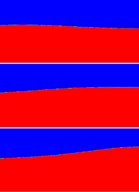
Figure 2 presents the volume fraction of water at different times of the simulation before the impact on the wall till the time of maximum height.

The following table gives the maximal height and and corresponding time of the wave against the wall. The discrepancies may come from the fact that the analytical developments were performed whithout taking into account the friction effects when waves interacts with walls.
| Mesh | Height | Time |
|---|---|---|
| 512x64 | 0.140651353646716 | 1.88965000000014 |
| 1024x128 | 0.141309095613568 | 1.87670000000026 |
| 2048x256 | 0.141929346450831 | 1.88072500000033 |
| Wave th. | 0.140206 | 1.8 |
[1] Lubin P., Lemonnier H., Test-case no 33: propagation of solitary waves in constant depths over horizontal beds. Multiph. Sci. Technol. 16, 239–250, 2004.
[2] Lubin P., Chanson H., Glockner S., Large Eddy Simulation of turbulence generated by a weak breaking tidal bore, Environmental Fluid Mechanics, vol. 10, no. 5, pp. 587-602, 2010.
[3] Su C.H., Mirie R.M., On head-on collision between two solitary waves, Journal of Fluid Mechanics, 98:509-525, 1994.